Item:0


Tel:86-0755-23283620,
MP:86-13725501611
Mail:service@kewodrive.com, Skye:liyucheng0211


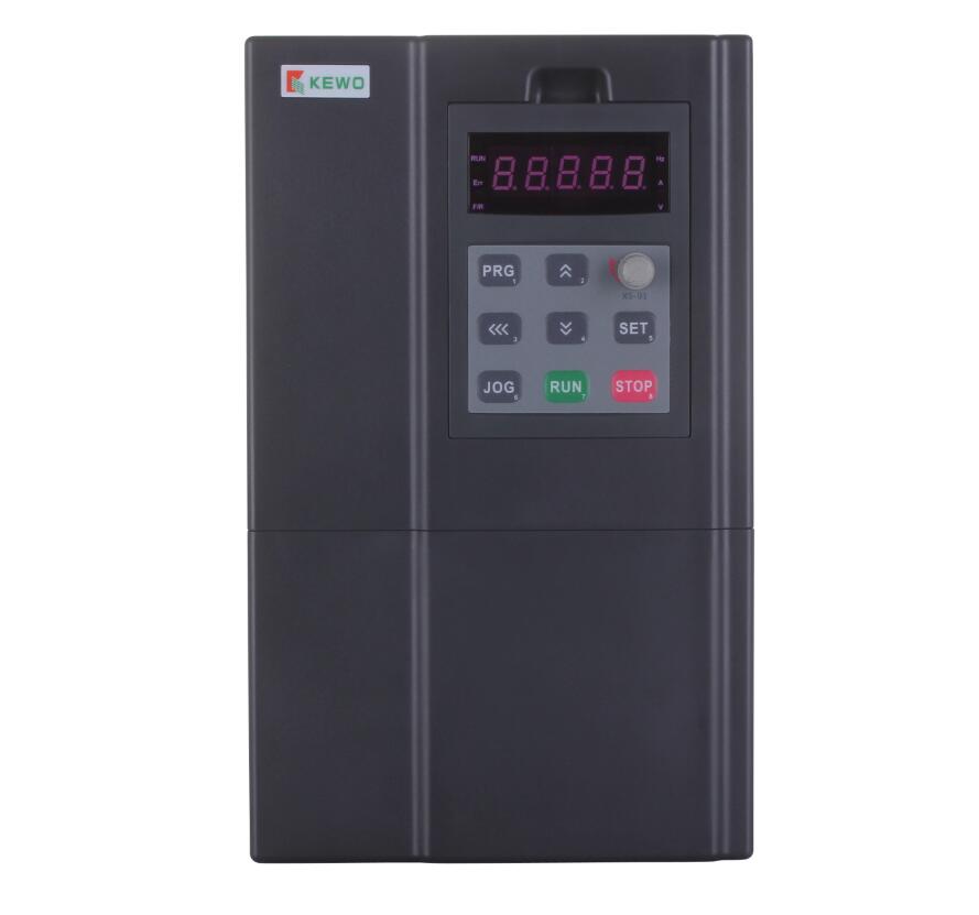
PV800 Solar Pumps Inverter
PV800 Solar Pump Inverter For PMSM & AM
The PV800 series solar pump inverter ( also can Solar Pump VFD) is a green energy products with new solar MPPT technology, which developed based on PV800 series motor frequency inverter, focusing on driving 3 phase AC pumps including AC induction pumps or high efficiency pumps with permanent magnet synchronous motor (PMSM) technology.
Compare to on grid or off grid solar inverter, it has soft starter, and multiple functions of motor protection, and very high competitive price.
Product Features
*Suitable for driving all 1/3 phase synchronous induction AC pumps, for PMSM high speed pumps is option.
*Multiple control modes, local control, auto start/stop, GPRS remote control.
*Maximum power point tracking (MPPT) with fast response speed and stable operation
*Dry run (under load ) protection, Water tank fulling detect, Maximum current of pump protection
*Low stop frequency protection, sleep/ wake up function when lack/enough of sunlight radiation.
*Dual mode input, compatible with DC and AC power input, low and wide range voltage input.
*The PQ (Power/Flow) performance curve enables calculating the flow output from the pump
*Multiple pumps protection function, short circuit, phase missing, over current, over voltage...
*Ambient temperature for using: -10 to +55˚C.
PV800 solar pump inverter models option:
2T, 150vdc to 450vdc input, for 3 phase 220VAC Pumps.
4T, 250/350 to 800VDC input, for 3 phase 380VAC Pumps.
5T, 350-900VDC input, for 3 phase 480VAC Pumps.
| 2.3. PV350/800 serial solar pump inverter model list | ||||||||
| SN | Models |
Rate current |
Output voltage ( 3PH VAC) | Applicable for pumps | Packing size | MPPT voltage (VDC) |
GW Kgs |
|
| 2T series : 150 to 450 VDC or 220VAC input, Vmp 310VDC, 372VDC | ||||||||
| 1 | PV350-2T0.75GB | 4A | 0 – 220V | 0.75KW | 215*170*190 | 260 to 355 | 1.5 | |
| 2 | PV350-2T1.5GB | 7A | 0 -220V | 1.5KW | 215*170*190 | 260 to 355 | 1.5 | |
| 3 | PV350-2T2.2GB | 10A | 0 -220V | 2.2kw | 215*170*190 | 260 to 355 | 1.5 | |
| 4 | PV800-2T3.7G | 16A | 0 -220V | 3.7kw | 280*180*215 | 260 to 355 | 1.5 | |
| 5 | PV800-2TXXGB | ** | 0-220V | <75kw | No-standard | 260 to 355 | ** | |
| 4T series, 250/ 350 to 800 VDC or 380VAC, Vmp540VDC, Voc 648VDC | ||||||||
| 8 | PV800-4T1.5GB | 3.7A | 0-440V | 1.5KW | 280*180*215 | 486 to 650 | 3 | |
| 9 | PV800-4T2.2GB | 5A | 0-440V | 2.2KW | 280*180*215 | 486 to 650 | 3 | |
| 10 | PV800-4T3.7GB | 10A | 0-440V | 4.0KW | 280*180*215 | 486 to 650 | 3 | |
| 11 | PV800-4T5.5GB | 13A | 0-440V | 5.5KW | 320*215*250 | 486 to 650 | 4.3 | |
| 12 | PV800-4T7.5GB | 17A | 0-440V | 7.5KW | 320*215*250 | 486 to 650 | 4.5 | |
| 13 | PV800-4T11GB | 25A | 0-440V | 11KW | 390*275*285 | 486 to 650 | 6.5 | |
| 14 | PV800-4T15GB | 32A | 0-440V | 15KW | 390*275*285 | 486 to 650 | 6.6 | |
| 15 | PV800-4T18.5GB | 38A | 0-440V | 18.5KW | 445*205*315 | 486 to 650 | 12 | |
| 16 | PV800-4T22GB | 45A | 0-440V | 22KW | 445*205*315 | 486 to 650 | 12 | |
| 17 | PV800-4T30G | 60A | 0-440V | 30KW | 545*395*370 | 486 to 650 | 16 | |
| 18 | PV800-4T37G | 75A | 0-440V | 37KW | 660*420*415 | 486 to 650 | 16 | |
| 19 | PV800-4T45G | 90A | 0-440V | 45KW | 660*420*415 | 486 to 650 | 27 | |
| 20 | PV800-4T55G | 110A | 0-440V | 55KW | 700*480*410 | 486 to 650 | 35 | |
| 21 | PV800-4T75G | 150A | 0-440V | 75KW | 700*480*410 | 486 to 650 | 35 | |
| 22 | PV800-4T93G | 170A | 0-440V | 93KW | 700*480*490 | 486 to 650 | 53 | |
| 23 | PV800-4T110G | 210A | 0-440V | 110KW | 700*480*490 | 486 to 650 | 56 | |
| 25 | PV800-4T132G | 260A | 0-440V | 132KW | 780*540*510 | 486 to 650 | 71 | |
| 25 | PV800-4T160G | 300A | 0-440V | 160KW | 780*540*510 | 486 to 650 | 72 | |
| 26 | PV800-4T185G | 340A | 0-440V | 185KW | 1130*580*570 | 486 to 650 | 149 | |
| 27 | PV800-4T200G | 380A | 0-440V | 200KW | 1130*580*570 | 486 to 650 | 180 | |
PV350/800 series solar pump inverter specification
| ** Specification of Solar pump inverter specification when parameters H9.00 set to for 1. | |
| Recommended MPPT voltage range |
Vmp 260 to 355VDC for 2T ( For driving 220VAC pumps ) Vmp 486 to 650 VDC for 4T (For driving 380VAC pumps) |
| Recommended input Voc and Vmpp voltage |
Voc 355(VDC), Vmpp 310(VDC) for 2T model or 220V AC pumps Voc 620(VDC), Vmpp 540(VDC) for 4T model or 380V AC pumps |
| Motor(pump) type | Control for permanent magnet synchronous motor (PMSM )and asynchronous motor pumps ( all type 3 phase induction motor) |
| Rated output voltage | 3-Phase,110V/160V/220V. 3-phase, 220V/380V/460V |
| Output frequency range | 0~Maximum frequency 400Hz. |
| Efficiency | 99.2 to 99.6% |
| Over load capacity |
G type for submersible pumps, 150% rated current for 60s, 180% rated current for 3s P type for surface pump, 120% rated current for 60s, 150% rated current for 2s. |
| Solar pump control special performance | MPPT ( maximum power point tracking),auto/manual operation, dry run protection, low stop frequency protection, minimum power input, motor maximum current protection, flow calculating, energy generated calculating and water tank level detected. |
| Protection function | Phase loss protection, phase short circuit protection, ground to phase circuit protection , input and output short circuit protection. Stall protection, lightning protection, over heat protection. |
| Protection degree | IP20, Air force cooling |
| Running mode | MPPT or CVT |
| Altitude | Below 1000m; above 1000m, derated 1% for every additional 100m. |
|
Standard AC input backup circuit |
CE, Design based on AD800 series high performance inverter, more specification please refer to AD800 series vector control inverter operation manualDimensions |
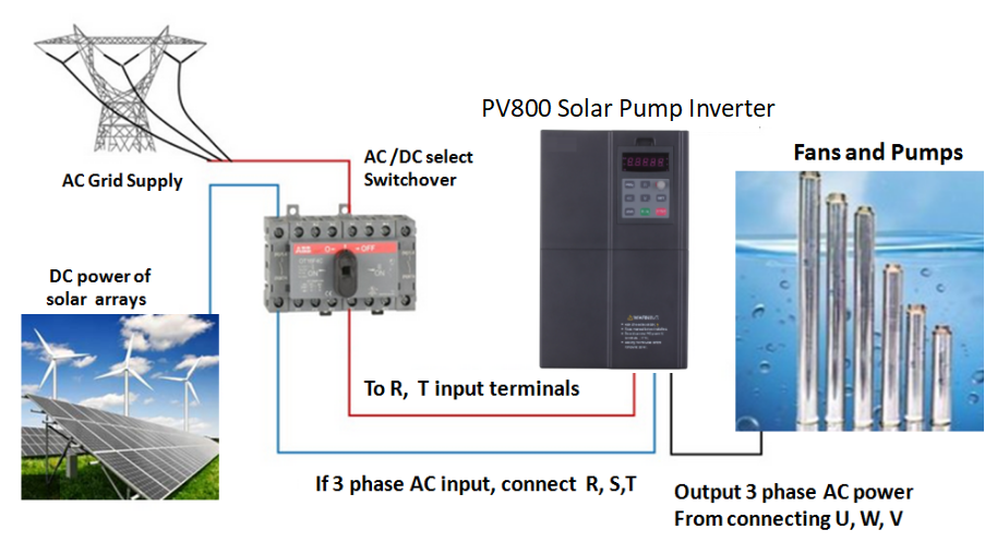
Installation and wiring of PV series solar pump inverter.
In generally, suggest user to connect a AC/DC manual switchover (S) to select if solar DC power input or AC grid input by manual.
Note:Forbidden connect DC power supply to P+ and PB of PV350, otherwise it will cause serious damage.
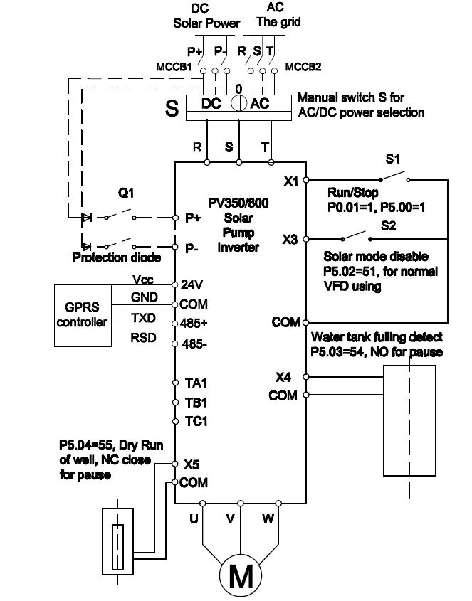
Wring steps
1. Recommend that connecting solar DC power supply to R, T terminals, ( also can connect P+ and P-, but please pay great attention of polarity connecting, positive to P+, negative to P-).
2. Connect a S1 switch to start inverter for pumping when set for terminals command control mode, and set P0.01=1, P5.00=1.
3. Connect S2 switch between X3 and COM when connect Ac grid power supply, when S2 is turn on, it will disable the solar pump control function, make inverter runs as a general purpose VFD, and set P5.02=51.
4. Connect float ball switch between X4 and COM for water tank fulling detecting, and set P5.03=54. when water is fulling ,NO switch of sensor will be turn on to stop pumping. Inverter will start again once the water level lower again.
5.Connect a float ball sensor normal close (NC) switch between X5 and COM in the well for dry run protecting. Ans set P5.04=55. If there are shortage of water in well, it will stop inverter pumping.
Solar pump inveter wiring
1. Connect P+ and P- power supply to R or T terminals
2. if need please connect AC/DC power selection switch
3. Connect a Run switch to X1 and COM for inverter starting
4. Conect a switch to disable solar pump control when power on AC grid
5. Connect a water tank ball sensor switch to X4 and COM for water fulling detecting
PV series solar pump inverter operation flow chat
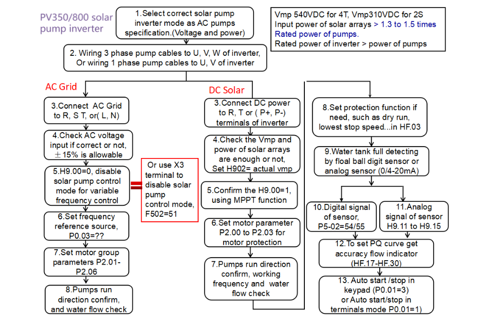
Operation steps:
1. Selecting correct inverter models according to the rated voltage, rated current of AC pumps.
Selecting to 2T series for 220VAC pump, the rated current of inverter should be bigger than pump’s.
Selecting 4T series for 380VAC pumps;the rated current of inverter should be bigger than pump’s.
Selecting 5T series for 480VAC pumps( Maximum DC voltage is 900VDC).
2. Check solar arrays input DC voltage and total input power if correct, check Voc open circuit voltage of solar arrays, and total input power of arrays.
| Input voltage, power solar arrays selection | ||||
| Pumps model | Inverter models | Vmp | Voc | Total Power of solar arrays |
| 110VAC pumps | 1S | 110*1.41=130VDC | 156VDC |
≧ (1.3 to 2.0) rated power of pumps It is also depend on the quality of solar panels. The more power input, the better performance. |
| 220VAC pumps | 2T | 220*1.41=310VDC | 372VDC | |
| 380VAC pumps | 4T (Max 800VDC) | 380*1.41=540VDC | 648VDC | |
| 480VAC pumps | 4T ( Max 900VDC) | 480*1.41=677VDC | 812VDC | |
Recommend solar panels arrays selection as following table
The user need to calculate how many solar panels connecting in series to get enough Vmp first, and then calculate how many strings of solar panels to get enough total power input.
| 265w, 38Voc (Open circuit voltage), 31Vmp ( Voltage at Pmax) | ||||
| Inverter models | Power of pump | Connection in series (PCS) (Vmp) | Connect in parallel ( Strings) Power | Total (PCS) |
| 1T (110VAC) | 0.75kw to 1.0kw | 5 PCS | 1* strings | 5*1=5 |
| 2T (220VAC) | 0.75kw to 1.5kw | 10PCS | 1* strings | 10*1=10 |
| 2T (220VAC) | 2.2kw | 11PCS | 1* strings | 11*1=11 |
| 4T(380VAC) | 0.75kw to 2.2kw | 18PCS | 1* strings | 18*1=18 |
| 4T(380VAC) | 3.7kw | 19PCS | 1* strings | 19*1=19 |
| 4T(380VAC) | 5.5kw | 18PCS | 2* strings | 18*2=36 |
| 4T(380VAC) | 7.5kw | 19pcs | 2* strings | 19*2=38 |
| 4T(380VAC) | 11kw | 18pcs | 3* strings | 18*3=54 |
| 4T(380VAC) | 15kw | 19pcs | 4* strings | 19*4=76 |
* For selecting 5T models for 480VAC pumps, the Vmp should be 480*1.41=677VDC, and around 811Voc.
3. Wiring as above inverter connection diagram, connect DC solar power supply to R, and T ( P+, and P-), connect pumps input cables to U, V, W of inverter , start switch s1, water fulling float ball switch s2, well dry run function sensor switch S3.
4. Set H9.02 value with actual Vmp of on site solar arrays for quick jump into MPPT calculating.
5. Confirm the inverter if work in solar pump MPPT control mode in H9.00=0.
6. Set motor group parameters for pump protection from P2.00 to P2.03. If the selecting inverter power as same as rated current of motor. It is no need to set this group parameters.
7. Check the water delivery, water outcome if good or not, check the pumps running direction is correct or not, if the running direction is not correct, please change any 2 phase order of U, V. W wiring.
8. Set auxiliary protection function, such as pumps lowest running speed, dry run protection, maximum current of pumps, minimum input power of solar arrays, PQ curve setting for accuracy flow and today flow indicating in HF group.
9.If need, connect water tank fulling sensor. There are two types water level sensor, digital and analog 0-20mA, connect as diagram showed.
10. If system request to run automatically, inverter start at early morning when sunlight is sufficient automatically, and stop at sunset when no enough radiation automatically, please connect a start switch S1 between X1 and COM, set P0.01=1 ( terminals control), and keep this switch in normal close status.
Note: H9 and HF both group parameters is special designed for solar pump control purpose only.
When H9.00=0, solar pump control will be disable, the output frequency is not depend on sunlight.
For the MPPT gain function is defined by H9.06, H9.07, H9.08 and H9.09. If set these parameters are bigger, the MPPt calculating is stronger.